The peripheral names and numbers used within this chapter are related
to MC68HC908AZ60 CPU. Other derivatives of HC08 family contain
analogous timers (with different name or structure). The 68HC908AZ60
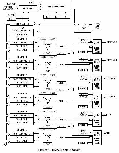
contains two timer modules TIMA and TIMB. Each one of these modules is
based on a 16-bit counter that can operate as a free-running counter or a
modulo up-counter. TIMA module has six channels and TIMB has two channels
that can be programmed independently as input capture or output capture
channels. Please see more details on timer modules in the CPU manual. For
details on another HC08/HCS08 family members please use CPU
Parameters Overview window or see a documentation of the appropriate
CPU.
|
| Figure 1 - Timer A block
diagram based on manufacturer documentation |
Timer peripheral selection, allocation and timing settings are
available in the Bean Inspector of the selected bean and overview of
peripheral allocation is also available in Target CPU or Peripheral
Usage windows. Please see chapters Bean
Inspector, Target CPU and Peripherals
Usage for details.
PWM
The PWM bean requires counter register, modulo register and one or two
compare registers according to the selected mode. It is possible to use
TIMA and TIMB devices. For the TIMA device up to 3 beans can use the
device in buffered mode, up to 6 beans can use it in unbuffered mode and
for the TIMB 1 bean can use the device in buffered mode and up to 2 in
unbuffered mode.
Example 1: Allocation of two PWM beans on the timer TIMA.
PWM#1 uses channel 2 and PWM#2 uses channels 4 and 5 in buffered mode. The
registers counter and modulo are shared by both beans (in this case the
same period of the generated signal is used for both the counters).
| |
bean PWM #1 in
unbuffered mode |
bean PWM #2 in
buffered mode |
| counter register |
shared |
shared |
| modulo register |
shared |
shared |
| compare register ch0 |
|
|
| compare register ch1 |
|
|
| compare register ch2 |
allocated |
|
| compare register ch3 |
|
|
| compare register ch4 |
|
allocated |
| compare register ch5 |
|
allocated |
Table 1 - TIMA Regiters Allocation For Example 1
Sharing peripheral with other beans
PWM bean can also share a timer peripheral with another timer beans:
TimerInt, RTIshared, TimeDate, FreeCntr8, FreeCntr16, FreeCntr32. The
limitation of the PWM when sharing the timer device with these beans is
that the period of the PWM must be equal to the full range of the counter
(The timing dialog for 'Period' property offers only values corresponding
to this condition). Shared beans cannot use the same channels of a timer.
PPG
The PPG bean requires counter register, modulo register and one or two
compare registers according the selected mode. There it is possible to use
TIMA and TIMB devices. It is not possible to share the un-allocated
channels with other beans which means that the PPG bean allocated the
whole peripheral.
Example: Allocation of registers of the PPG bean in buffered mode on
the timer TIMA.
Channels: 0,1,2 and 3 are free.
| |
bean PPG in buffered
mode |
| counter register |
allocated |
| modulo register |
allocated |
| compare register ch0 |
|
| compare register ch1 |
|
| compare register ch2 |
|
| compare register ch3 |
|
| compare register ch4 |
allocated |
| compare register ch5 |
allocated |
TimerOut
The TimerOut bean requires counter register, modulo register and one or
two compare registers according the selected mode. It is possible to use
TIMA and TIMB devices. For the TIMA device 3-6 TimerOut beans can be used
and for the TIMB device 1-2 TimerOut beans can be used.
Example:Allocation of registers with one TimerOut bean in buffered
mode on the timer TIMA.
Channels free: 1,2,3,4 and 5 are free. It is possible to allocate the
remaining registers. For example with the TimerOut, TimerInt , FreeCntr
etc. If more than one bean is used, the other ones work in shared mode.
The beans use common counters and modulo registers, and they have a
generated signal of the same period.
| |
bean TimerOut in
unbuffered mode |
| counter register |
Allocated (can be
shared) |
| modulo register |
Allocated (can be
shared) |
| compare register ch0 |
Allocated |
| compare register ch1 |
|
| compare register ch2 |
|
| compare register ch3 |
|
| compare register ch4 |
|
| compare register ch5 |
|
TimerInt, RTIshared, TimeDate, FreeCntr8, FreeCntr16, FreeCntr32
These beans require counter register, modulo register and eventually
compare register according the selected mode. There it is possible to use
TIMmod (PITmod), TIMA, TIMB and RTI devices. The TIMA device can use 3-6
TimerOut beans and the TIMB device can use 1-2 TimerOut beans.
Example:Allocation of registers with one Timer Int bean on the timer
TIMA.
Channels free: 1,2,3,4 and 5 are free. It is possible to allocate the
remaining registers, for example, with the beans of same type and also
with TimerOut beans. If more than one bean is used, the other ones work in
shared mode. The beans use a common counter and modulo register and a have
generated signal of the same period.
| |
TimerInt |
| counter register |
allocated (can be
shared) |
| moduloregister |
allocated (can be
shared) |
| compare register ch0 |
Allocated |
| compare register ch1 |
|
| compare register ch2 |
|
| compare register ch3 |
|
| compare register ch4 |
|
| compare register ch5 |
|
Sharing the timer device
Multiple TimerInt, RTIshared, TimeDate, FreeCntr8, FreeCntr16 and
FreeCntr32 beans can share the selected timer device. The limitation is
that the prescaler value needed to achieve a desired timing must be equal
for individual beans.
Example:Allocation of registers with more beans on the timer TIMA.
| |
RTIshared |
TimerInt |
TimerInt |
TimerOut |
| counter register |
shared |
shared |
shared |
shared |
| modulo register |
shared |
shared |
shared |
shared |
| compare register ch0 |
|
allocated |
|
|
| compare register ch1 |
|
|
|
|
| compare register ch2 |
|
|
allocated |
|
| compare register ch3 |
|
|
|
|
| compare register ch4 |
|
|
|
allocated |
| compare register ch5 |
|
|
|
|
EventCntr8, EventCntr16, EventCntr32
These beans require counter register and modulo register. It is
possible to use the beans for TIMA and TIMB devices. These beans allocate
whole peripheral, it is not possible to share unallocated channels with
other beans.
Example:Allocation of registers with EventCntr16 bean on the timer
TIMA.
| |
EventCntrl16 |
| counter register |
allocated |
| modulo register |
allocated |
| compare register ch0 |
|
| compare register ch1 |
|
| compare register ch2 |
|
| compare register ch3 |
|
| compare register ch4 |
|
| compare register ch5 |
|
Capture
These beans require counter register, modulo register and compare
register as input capture latch. It is possible to use the beans for TIMA
and TIMB devices.
Example:Allocation of registers with Capture bean on the timer TIMA.
Channels: 0,2,3,4 and 5 are free.
| |
Capture |
| counter register |
allocated (can be
shared) |
| modulo register |
allocated (can be
shared) |
| compare register ch0 |
|
| compare register ch1 |
allocated |
| compare register ch2 |
|
| compare register ch3 |
|
| compare register ch4 |
|
| compare register ch5 |
|