|
Target CPU Window
Processor Expert | View | Target
CPU Package
Processor Expert | View | Target
CPU Block Diagram
Processor Expert | View | Target
CPU Structure
This window displays selected target CPU with its peripherals
and pins (possible data directions of single pins are indicated by blue
arrows on the CPU package when a bean uses these pins). Several display
modes are supported. It is possible to switch the display mode by
pushing buttons in the left side menu of the window.
Control Buttons
The meanings of the buttons on the left side are:
 Rotates CPU - rotate the CPU 90 degrees to the right.
 Show user names on CPU package - switches the pins' and
peripherals' default names (from catalog) for user-defined names.
Show user names on CPU package - switches the pins' and
peripherals' default names (from catalog) for user-defined names.
 Zoom in - increases the detail level of the view. The whole
picture might not fit the viewing area.
Zoom in - increases the detail level of the view. The whole
picture might not fit the viewing area.
 Zoom out - decreases the detail level of the view. Processor
Expert tries to fit the whole picture to the viewing area.
Zoom out - decreases the detail level of the view. Processor
Expert tries to fit the whole picture to the viewing area.
 Show CPU package and peripheral - switches to the CPU
package view mode.
Show CPU package and peripheral - switches to the CPU
package view mode.
 Show BGA CPU package - switches to the CPU BGA
package view mode.
Show BGA CPU package - switches to the CPU BGA
package view mode.
 Show CPU block diagram - switches to the CPU
block diagram view mode.
Show CPU block diagram - switches to the CPU
block diagram view mode.
 Show CPU peripherals in a list - switches to the CPU
peripherals list view mode.
Show CPU peripherals in a list - switches to the CPU
peripherals list view mode.
View Modes
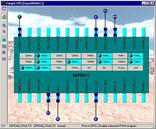
- CPU package mode - a realistic view of the
CPU package with pins and peripherals. Each allocated peripheral
contain an icon of the bean that allocates it. For allocated pins
also the bean icon with the connection is shown.
|
| Figure 1 - Target
CPU - CPU package view mode |
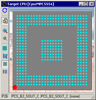
- CPU BGA package mode - This mode is
available only for CPUs with grid-array pins layout. It is similar
to the package mode, but the pins hidden by package are shown and
the peripherals are hidden.
|
| Figure 2 - Target
CPU - BGA CPU package view mode |
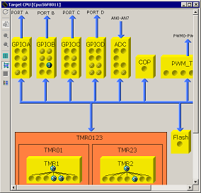
- CPU block diagram mode - a view of the CPU
block diagram based on the documentation of the CPU manufacturer.
Every part of the CPU is represented by a block. Every block that
contains a resources that can be allocated by Processor Expert
contains the slots for every resource (e.g. pin or channel). If the
resource is allocated, the slot contains the icon of the allocating
bean.
|
| Figure 3 - Target
CPU - MCU block diagram view mode |
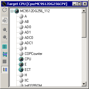
- CPU peripherals list - a list of all
peripherals of the CPU is displayed. If a peripheral is unallocated
by Processor Expert, it is displayed as a gray icon. Otherwise, the
icon of the bean that allocates the peripheral is displayed. The
same mouse commands are available as in the other view-modes, except
the operations with pins (pins are not visible in this mode).
|
| Figure 4 - Target
CPU - Peripherals List Mode |
Pins
The following information about each pin is displayed on the CPU
picture:
(all pins are displayed only in the CPU package view mode)
- pin name (default or user-defined)
- icon of a bean that uses (allocates) the pin
- direction of the pin (input, output, or input/output)
symbolized by blue arrows, if a bean is connected
Pin names are shortened and written either from left to right or from
up to down and are visible only if there is enough space in the diagram.
Some signals and peripherals cannot be used by the user because they
are allocated by special devices such as power signals, external or data
bus. The special devices are indicated by a special blue icons, for
example  . The
allocation of peripherals by special devices can be influenced by CPU
properties. . The
allocation of peripherals by special devices can be influenced by CPU
properties.
Hints
Pin hint contains:
- number of the pin (on package)
- both names (default and user-defined)
- owner of the pin (bean that allocates it)
- short pin description from CPU database
Bean icon hint contains:
- bean name
- bean type
- bean description
Shared Pins
If a pin is shared by multiple beans, the line connecting the pin to
the bean has a red color. See chapter Pin
Sharing for details.

|
| Figure 5 - Shared pin
connection |
On-chip peripherals
The following information about each on-chip peripheral is displayed
on the CPU package:
- peripheral device name (default or user-defined)
- icon of the bean that uses (allocates) the
peripheral device
Peripheral device hint contains:
- peripheral device name
- owner of the pin (bean that allocates it)
- short peripheral device description
Hint on icon contains:
- bean name
- bean type
- bean description
If a peripheral is shared by several beans (for example: several
beans may use single pins of the same port), the  icon is displayed.
Note for peripherals working in several modes:
Some peripherals work in several modes and these peripherals can be
represented by a several devices in the CPU databases. For example, the
device "TimerX_PPG" and "TimerX_PWM" represents
TimerX in PPG and in PWM mode. These devices can be displayed on the CPU
package, but they are also represented as a single block in the MCU
block diagram.
Mouse Operations For Individual Items
- Single click on a bean icon selects the bean in the
Project panel.
- Double click on a bean icon opens its Bean
Inspector and selects the property specifying the peripheral
used by the bean.
- Double click on a peripheral opens the
simple item structure view.
- Double click on an
icon opens a selection menu with all the beans that use single parts
of the peripheral. Selecting one bean opens it in the Bean
Inspector.
- Right button click on a bean icon opens the Bean
pop-up menu. If the Bean Inspector is invoked from this pop-up
menu, an appropriate property allocating the used peripheral is
selected.
- Right button click on an
icon opens selection menu with all the beans that use single parts
of the peripheral. Selecting one bean opens the Bean
pop-up menu.
- Right click on the peripheral opens the Peripheral
Pop-up menu (see below).
Peripheral/Pin Pop-up Menu
The following commands are available in the pop-up menu:
- Show
Peripheral Initialization - shows initialization values of
all "control, status and data" registers. This option is
supported for all devices displayed on a CPU package. See chapter Peripheral
Initialization for details.
- Show
Peripheral Structure - opens the peripheral's structure view
- (it is supported for I/O ports, timer's counters, serial ports.
This option is also supported for devices working in several modes
in the CPU block diagram. A list of represented devices for these
modes is displayed.
- Show
Peripheral Usage - shows which part of the peripheral is used
by the application (visible after code generation). This option is
supported for I/O ports and pins, timers, A/D converters and A/D
channels, CAN, serial ports, watchdog, internal memories (EEPROM and
FLASH). See chapter Peripherals
Usage for details.
- Rename
Peripheral - allows you to rename the selected peripheral. It
is supported for I/O ports and pins, watchdog and timers (counters,
compare and capture registers, free running devices), A/D converters
and A/D channels, CAN, serial ports.
- Search Related
Info In CPU PDF Documentation displays PDF Search window and
finds the information about the peripheral in the appropriate CPU
documentation. It is also possible to search for any keyword in the
CPU documentation based on the original manufacturer's CPU manual. (This
item is available on the package and on the CPU block only.) See
chapter PDF Search for details.
- Add Bean/Template
- adds a bean or template for the appropriate peripheral: all
available beans and templates suitable for the selected peripheral
are listed. The beans and templates in the list are divided by a
horizontal line. It is possible to add only beans or templates which
are applicable for the peripheral. It means that is possible to add
the bean or template only if the peripheral is not already allocated
to another bean or beans. The beans/templates that cannot be added
to the peripheral are grayed in the pop-up menu as unavailable. This
option is supported for all devices displayed on CPU package.
- Help on Target
CPU Window - displays help for the current window
|